Description
| Operating principle | 2-way flow limiter with volumetric flow control | |
| Outlet pipes | 1 | |
| Lubricant | environmentally friendly mineral and synthetic oils | |
| Viscosity | 20–600 mm2/With | |
| Consumption1) | 25–90 l/min | 52.8–190 pints/min |
| Operating temperature | from 0 to 70 °C | from 32 to 158 °F |
| Working pressure | 6–50 bar | 87–725 psi |
| Differential pressure | >6 bar | >87 psi |
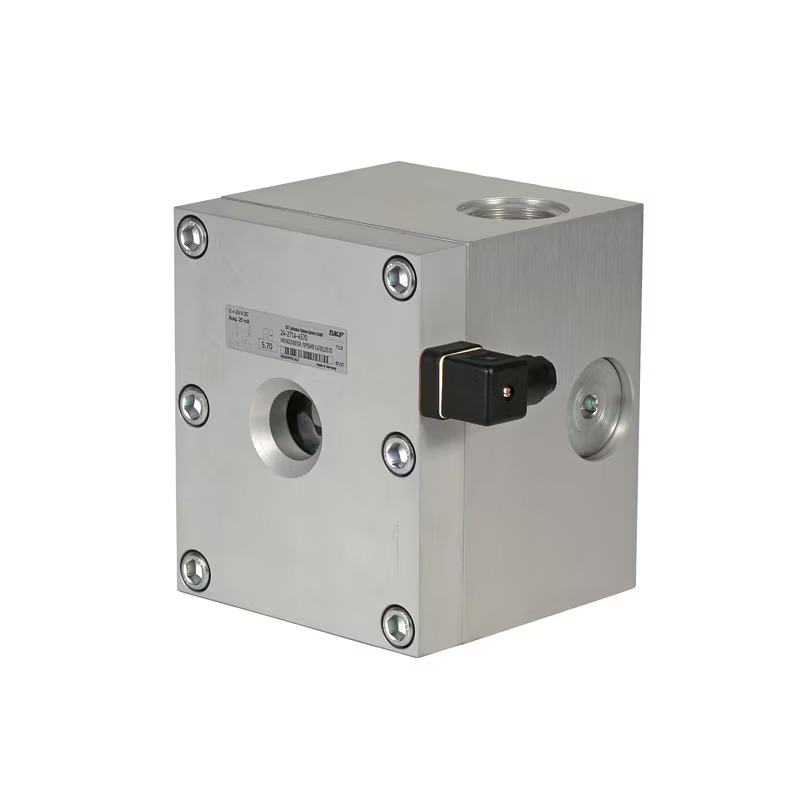
| Electrical connection | Hall sensor | |
| Voltage | 24 V DC current ± 10 %, max. 20 mA | |
| Material | AlCuPb F38, neutral anodizing | |
| Compound | plug, DIN 43650 | |
| Protection class | IP 65 | |
| Dimensions | 150 × 180 × 190 mm | 5.91 x 7.09 x 7.48 inches |
| Installation position | any | |
| Options | ATEX version | |
| The product can be configured using a configuration code. The flow rate must be adjusted according to the insert nozzle size, as shown in the table below. | |
| 24-2714-0… | SMB14 without monitoring, for nozzle indexes 570–960, insert nozzle size = see table below |
| 24-2714-1… | SMB14 without monitoring, for injector indexes 000–170, insert nozzle size = see table below |
| 24-2714-4… | SMB14 with electrical monitoring 1), for injector with indexes 570–960, insert injector size = see table below |
| 24-2714-5… | SMB14 with electrical monitoring 1), for injector with indexes 000–170, insert injector size = see table below |
| ATEX versions are available upon request for ATEX designs only (EX II 2G with TX Gb, EX II 2D with TX Db), without monitoring or with a piston sensor. Please add "ATEX" to the end of the part number. More detailed information is available in product catalog. |
|
| Article | Consumption | Injector index | Nozzle | |
| l/min | pints/min | ∅ mm | ||
| 44-0455-2357 | 25 | 52,8 | 570 | 5,70 |
| 44-0455-2360 | 30 | 63,4 | 630 | 6,30 |
| 44-0455-2363 | 35 | 73,9 | 680 | 6,80 |
| 44-0455-2365 | 40 | 84,5 | 730 | 7,30 |
| 44-0455-2367 | 45 | 95,1 | 780 | 7,80 |
| 44-0455-2369 | 50 | 105,7 | 820 | 8,20 |
| 44-0455-2371 | 55 | 116,2 | 870 | 8,70 |
| 44-0455-2373 | 60 | 126,8 | 910 | 9,10 |
| 44-0455-2374 | 65 | 137,4 | 960 | 9,60 |
| 44-0455-2375 | 70 | 147,9 | 000 | 10,00 |
| 44-0455-2376 | 75 | 158,5 | 040 | 10,40 |
| 44-0455-2377 | 80 | 169,0 | 080 | 10,80 |
| 44-0455-2378 | 90 | 190,2 | 170 | 11,70 |
| Article | Description |
| 44-0758-2049 | viewing window D45×12 |
| 24-0404-2311 | Seal kit: D32/45×05 gasket; 44×3 O-ring; 90×3 O-ring |
| 24-1882-2029 | nest |
| Part number | Description |
| 24-1883-3017 | SMB 14 without nozzle, with electrical monitoring |