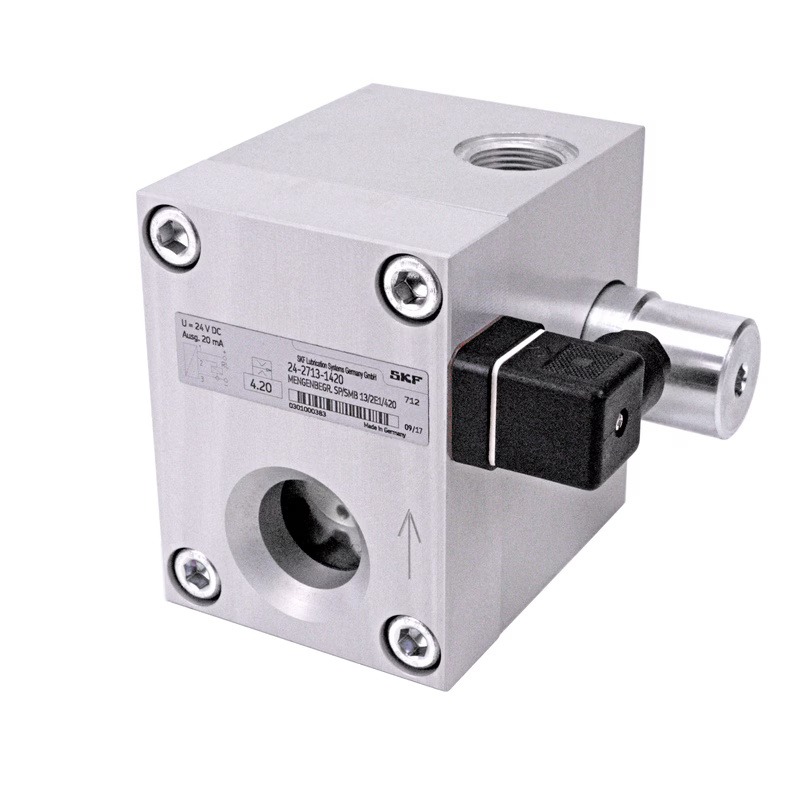
Description
| Operating principle | 2-way flow limiter with volumetric flow control | |
| Exits | 1 | |
| Lubricant | environmentally friendly mineral and synthetic oils | |
| Viscosity | 20–600 mm2/With | |
| Consumption1) | 6.0–38 l/min | 12.6–80.3 pints/min |
| Operating temperature | from 0 to +70 °C | from +32 to 158 °F |
| Working pressure | 6–50 bar | 87–725 psi |
| Differential pressure | >6 bar | >87 psi |
| Electrical connection | Hall sensor | |
| Voltage | 24 V DC current ± 10 %, max. 20 mA | |
| Material | AlCuPb F38, neutral anodizing | |
| Compound | plug, DIN 43650 | |
| Protection class | IP 65 | |
| Dimensions | 115 × 120 × 128.5 mm | 4.53 x 4.72 x 5.06 inches |
| Installation position | any | |
| Options | ATEX version for Ex II 2G with TX Gb, Ex II 2D with TX Db |
|
| The product can be configured using a configuration code. The flow rate must be adjusted according to the insert nozzle size, as shown in the table below. | |
| 24-2713-0… | SMB13 without monitoring, … plug-in nozzle size = see table below |
| 24-2713-1… | SMB13 with electrical monitoring, … insert nozzle size = see table below |
| 24-2713-2… | SMB13 with monitoring for ATEX, … plug-in nozzle size = see table below |
| 24-2713-3… | SMB13 without monitoring for ATEX, … plug-in nozzle size = see table below |
| ATEX versions are available upon request for ATEX only (EX II 2G with TX Gb, EX II 2D with TX Db), without monitoring, or with a piston sensor. Add "ATEX" to the end of the part number. More detailed information is provided in the product catalogue. |
|
| Part number | Consumption | Nozzle | |
| l/min | pints/min | ∅ mm | |
| 250 | 6,00 | 12,6 | 2,50 |
| 260 | 6,50 | 13,7 | 2,6 |
| 270 | 6,75 | 14,2 | 2,7 |
| 280 | 7,00 | 14,8 | 2,8 |
| 290 | 7,50 | 15,6 | 2,9 |
| 300 | 8,00 | 16,9 | 3,0 |
| 310 | 8,75 | 18,5 | 3,1 |
| 320 | 9,25 | 19,5 | 3,2 |
| 330 | 9,75 | 20,6 | 3,3 |
| 340 | 10,50 | 22,1 | 3,4 |
| 350 | 11,00 | 23,2 | 3,5 |
| 360 | 11,50 | 24,3 | 3,6 |
| 370 | 12,00 | 25,4 | 3,7 |
| 380 | 12,75 | 26,9 | 3,8 |
| 390 | 13,50 | 28,5 | 3,9 |
| 400 | 14,00 | 29,6 | 4,0 |
| 410 | 14,75 | 31,1 | 4,1 |
| 420 | 15,50 | 32,8 | 4,2 |
| 430 | 16,00 | 33,8 | 4,3 |
| 440 | 16,75 | 35,4 | 4,4 |
| 450 | 17,50 | 26,9 | 4,5 |
| 460 | 18,00 | 38,0 | 4,6 |
| 470 | 18,75 | 39,6 | 4,7 |
| 480 | 19,50 | 41,2 | 4,8 |
| 490 | 20,25 | 42,8 | 4,9 |
| 500 | 21,00 | 44,4 | 5,0 |
| 510 | 21,75 | 45,9 | 5,1 |
| 520 | 22,50 | 47,6 | 5,2 |
| 530 | 23,25 | 49,1 | 5,3 |
| 540 | 24,00 | 50,7 | 5,4 |
| 550 | 25,00 | 52,8 | 5,5 |
| 560 | 26,00 | 54,9 | 5,6 |
| 570 | 27,00 | 57,0 | 5,7 |
| 580 | 28,00 | 59,1 | 5,8 |
| 600 | 30,00 | 63,4 | 6,0 |
| 650 | 34,00 | 71,9 | 6,5 |
| 690 | 38,00 | 80,3 | 6,9 |
| Article | Description |
| 44-0758-2049 | viewing window D45×12 |
| 24-0404-2310 | Seal kit: D32/45×05 gasket; 44×3 O-ring; 90×3 O-ring |
| 24-1882-2029 | nest |
| Part number | Description |
| 24-1883-3016 | SMB 13 without nozzle, with electrical monitoring |