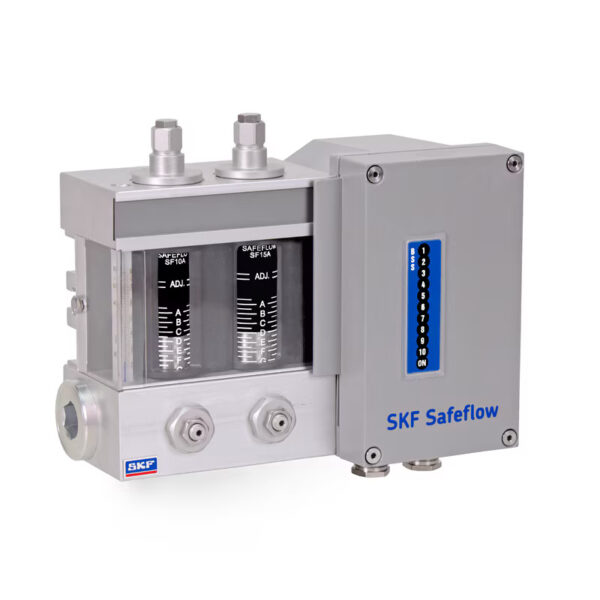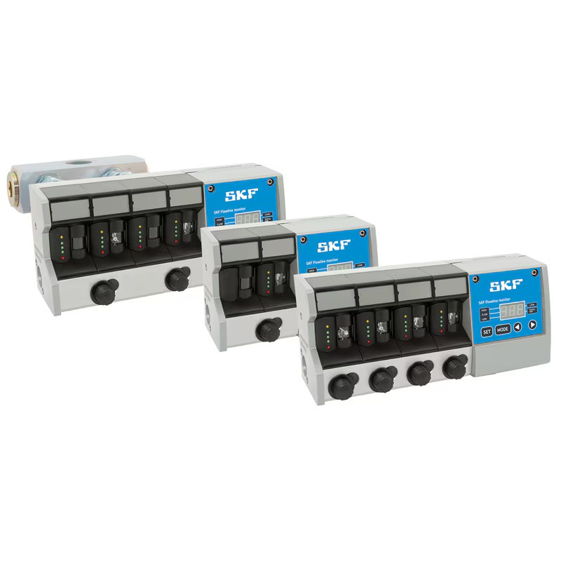
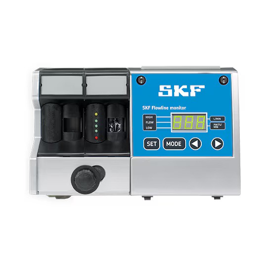
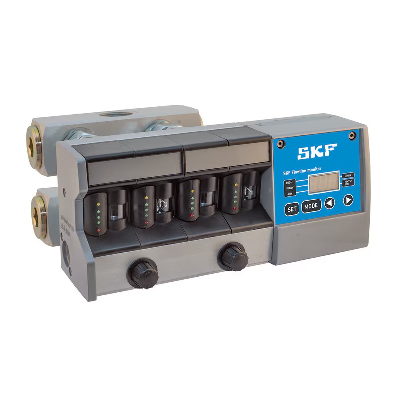
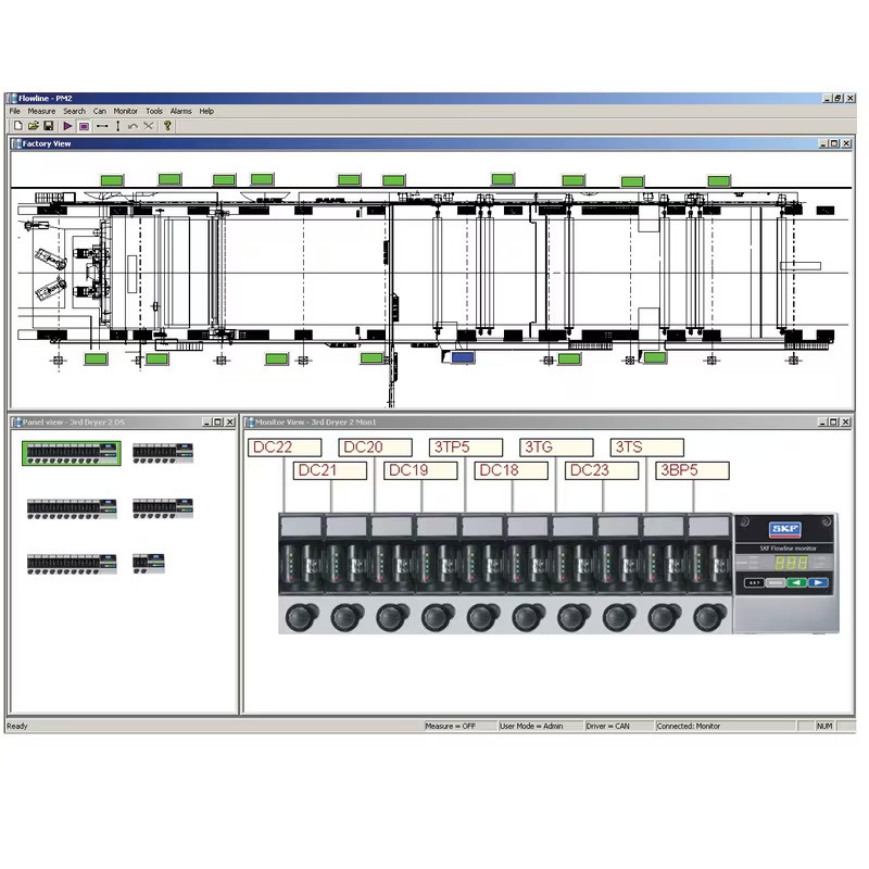
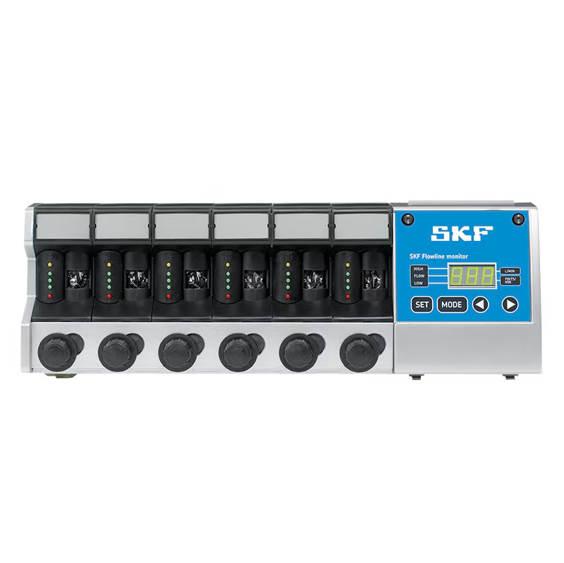
Description
| FL15 | FL50 | FL100 | |
| Operating principle | Flow meter with built-in monitoring tools | ||
| Consumption | 0.1–15.0 l/min 0.2–30.0 pints/min |
15–50 l/min 30–100 pints/min |
50–100 l/min 100–200 pints/min |
| Group size | 2, 4, 6, 8, 10 | 1, 2 | 1 |
| Lubricant | Oil | ||
| Viscosity range | 32–1000 mm²/s | ||
| Working pressure | max 10 bar(145 psi) | ||
| Operating temperature | from 0 to +65 °C (32 to 150 °F) | ||
| Protection class | IP 65 | ||
| Power supply | 20-36 VDC, 24 VAC (-20 to +5 %) | ||
| Energy consumption | 5 W | ||
| Signal relay | Dry contact; Max. load 30VDC/1A, 120VAC/1A, resistive load |
||
| Input connections | BSPP G 1 or NPT 1 | BSPP 2× G 1 or 2× NPT 1 | |
| Output connections | BSPP G 1/2 or NPT 1/2 | BSPP G 1 or NPT 1 | BSPP 2× G 1 or 2× NPT 1 BSPP 1× G 1 1/4 or 1× NPT 1 1/4 |
| Dimensions in mm min. Max. |
226 x 150 x 106 618 x 150 x 106 |
226 x 150 x 106 | 324 x 150 x 222 324 x 150 x 230 |
| Dimensions in inches min. Max. |
8.89 x 5.9 x 4.17 24.33 x 5.9 x 4.17 |
8.89 x 5.9 x 4.17 | 12.76 x 5.9 x 8.74 12.76 x 5.9 x 9.05 |
| Order number | Designation | Number of flow meters | Flow meter consumption | Interface board | |
| l/min | pints/min | ||||
| 13120202 | FL15-02-R | 2 | 0.1–15 | 0.2–32 | emergency signal relay |
| 13120204 | FL15-04-R | 4 | 0.1–15 | 0.2–32 | emergency signal relay |
| 13120206 | FL15-06-R | 6 | 0.1–15 | 0.2–32 | emergency signal relay |
| 13120208 | FL15-08-R | 8 | 0.1–15 | 0.2–32 | emergency signal relay |
| 13120210 | FL15-10-R | 10 | 0.1–15 | 0.2–32 | emergency signal relay |
| 13120300 | FL50-R | 1 | 15–50 | 32–105 | emergency signal relay |
| 13120316 | FL50-02-R | 2 | 15–50 | 32–105 | emergency signal relay |
| 13127800 | FL100-01-R | 1 | 50–100 | 105–210 | emergency signal relay |
| 13120212 | FL15-02-R-CAN | 2 | 0.1–15 | 0.2–32 | CAN bus module |
| 13120214 | FL15-04-R-CAN | 4 | 0.1–15 | 0.2–32 | CAN bus module |
| 13120216 | FL15-06-R-CAN | 6 | 0.1–15 | 0.2–32 | CAN bus module |
| 13120218 | FL15-08-R-CAN | 8 | 0.1–15 | 0.2–32 | CAN bus module |
| 13120220 | FL15-10-R-CAN | 10 | 0.1–15 | 0.2–32 | CAN bus module |
| 13120310 | FL50-R-CAN | 1 | 15–50 | 32–105 | CAN bus module |
| 13120317 | FL50-02-R-CAN | 2 | 15–50 | 32–105 | CAN bus module |
| 13127808 | FL100-01-R-CAN | 1 | 50–100 | 105–210 | CAN bus module |
| 13120342 | FL15-02-R-RCM | 2 | 0.1–15 | 0.2–32 | relay and CAN bus module |
| 13120344 | FL15-04-R-RCM | 4 | 0.1–15 | 0.2–32 | relay and CAN bus module |
| 13120346 | FL15-06-R-RCM | 6 | 0.1–15 | 0.2–32 | relay and CAN bus module |
| 13120348 | FL15-08-R-RCM | 8 | 0.1–15 | 0.2–32 | relay and CAN bus module |
| 13120350 | FL15-10-R-RCM | 10 | 0.1–15 | 0.2–32 | relay and CAN bus module |
| 13120312 | FL50-R-RCM | 1 | 15–50 | 32–105 | relay and CAN bus module |
| 13120318 | FL50-02-R-RCM | 2 | 15–50 | 32–105 | relay and CAN bus module |
| 13127802 | FL100-01-R-RCM | 1 | 50–100 | 105–210 | relay and CAN bus module |
| 13120362 | FL15-02-R-mA | 2 | 0.1–15 | 0.2–32 | analog module |
| 13120364 | FL15-04-R-mA | 4 | 0.1–15 | 0.2–32 | analog module |
| 13120366 | FL15-06-R-mA | 6 | 0.1–15 | 0.2–32 | analog module |
| 13120368 | FL15-08-R-mA | 8 | 0.1–15 | 0.2–32 | analog module |
| 13120370 | FL15-10-R-mA | 10 | 0.1–15 | 0.2–32 | analog module |
| 13120314 | FL50-R-mA | 1 | 15–50 | 32–105 | analog module |
| 13120319 | FL50-02-R-mA | 2 | 15–50 | 32–105 | analog module |
| 13127804 | FL100-01-R-mA | 1 | 50–100 | 105–210 | analog module |
| 13120180 | FL100 outlet block G 1 1/4 | — | — | — | — |
| Order number | Designation | Number of flow meters | Flow meter consumption | Interface board | |
| l/min | pints/min | ||||
| 13120222 | FL15-02-U | 2 | 0.1–15 | 0.2–32 | emergency signal relay |
| 13120224 | FL15-04-U | 4 | 0.1–15 | 0.2–32 | emergency signal relay |
| 13120226 | FL15-06-U | 6 | 0.1–15 | 0.2–32 | emergency signal relay |
| 13120228 | FL15-08-U | 8 | 0.1–15 | 0.2–32 | emergency signal relay |
| 13120230 | FL15-10-U | 10 | 0.1–15 | 0.2–32 | emergency signal relay |
| 13120320 | FL50-U | 1 | 15–50 | 32–105 | emergency signal relay |
| 13120336 | FL50-02-U | 2 | 15–50 | 32–105 | emergency signal relay |
| 13127810 | FL100-01-U | 1 | 50–100 | 105–210 | emergency signal relay |
| 13120232 | FL15-02-U-CAN | 2 | 0.1–15 | 0.2–32 | CAN bus module |
| 13120234 | FL15-04-U-CAN | 4 | 0.1–15 | 0.2–32 | CAN bus module |
| 13120236 | FL15-06-U-CAN | 6 | 0.1–15 | 0.2–32 | CAN bus module |
| 13120238 | FL15-08-U-CAN | 8 | 0.1–15 | 0.2–32 | CAN bus module |
| 13120240 | FL15-10-U-CAN | 10 | 0.1–15 | 0.2–32 | CAN bus module |
| 13120330 | FL50-U-CAN | 1 | 15–50 | 32–105 | CAN bus module |
| 13120337 | FL50-02-U-CAN | 2 | 15–50 | 32–105 | CAN bus module |
| 13127810 | FL100-01-U-CAN | 1 | 50–100 | 105–210 | CAN bus module |
| 13120352 | FL15-02-U-RCM | 2 | 0.1–15 | 0.2–32 | relay and CAN bus module |
| 13120354 | FL15-04-U-RCM | 4 | 0.1–15 | 0.2–32 | relay and CAN bus module |
| 13120356 | FL15-06-U-RCM | 6 | 0.1–15 | 0.2–32 | relay and CAN bus module |
| 13120358 | FL15-08-U-RCM | 8 | 0.1–15 | 0.2–32 | relay and CAN bus module |
| 13120360 | FL15-10-U-RCM | 10 | 0.1–15 | 0.2–32 | relay and CAN bus module |
| 13120331 | FL50-U-RCM | 1 | 15–50 | 32–105 | relay and CAN bus module |
| 13120338 | FL50-02-U-RCM | 2 | 15–50 | 32–105 | relay and CAN bus module |
| 13127812 | FL100-01-U-RCM | 1 | 50–100 | 105–210 | relay and CAN bus module |
| 13120372 | FL15-02-U-mA | 2 | 0.1–15 | 0.2–32 | analog module |
| 13120374 | FL15-04-U-mA | 4 | 0.1–15 | 0.2–32 | analog module |
| 13120376 | FL15-06-U-mA | 6 | 0.1–15 | 0.2–32 | analog module |
| 13120378 | FL15-08-U-mA | 8 | 0.1–15 | 0.2–32 | analog module |
| 13120380 | FL15-10-U-mA | 10 | 0.1–15 | 0.2–32 | analog module |
| 13120334 | FL50-U-mA | 1 | 15–50 | 32–105 | analog module |
| 13120339 | FL50-02-U-mA | 2 | 15–50 | 32–105 | analog module |
| 13127816 | FL100-01-U-mA | 1 | 50–100 | 105–210 | analog module |
| 13120182 | FL100 outlet block NPT 1 1/4 | — | — | — | — |
Configure the product, download the CAD file