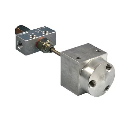
Description
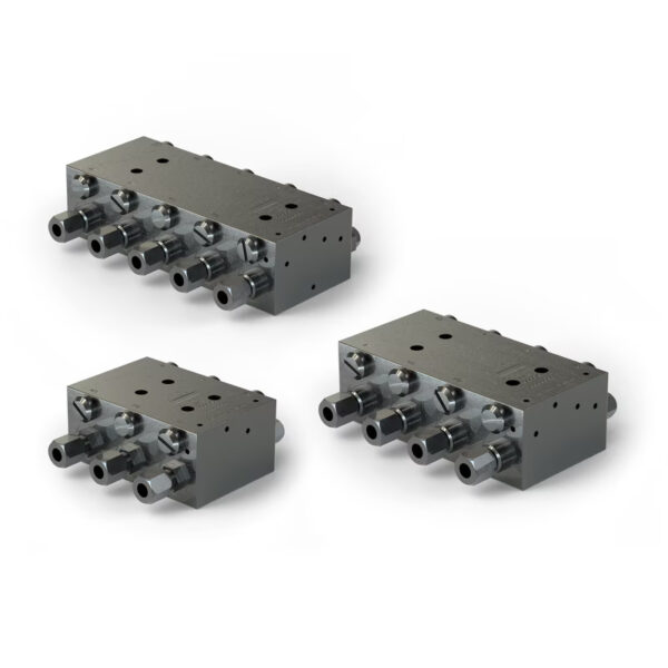
| Operating principle | Flow divider | |
| Exits | 1 | |
| Lubricant | Mineral or synthetic oil compatible with NBR rubber | |
| Viscosity | max 3000 mm2/With | |
| Response pressure, air | max 10 bar | max 145 psi |
| Response pressure, oil | max 5 bar | max 73 psi |
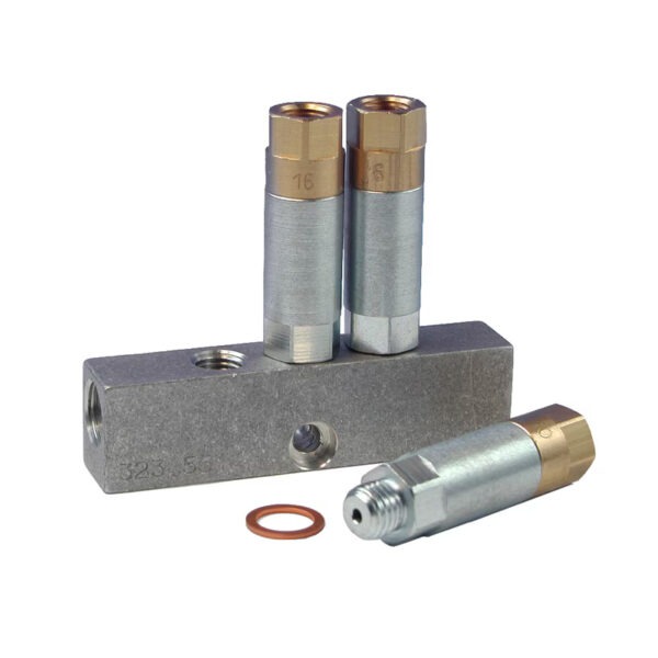
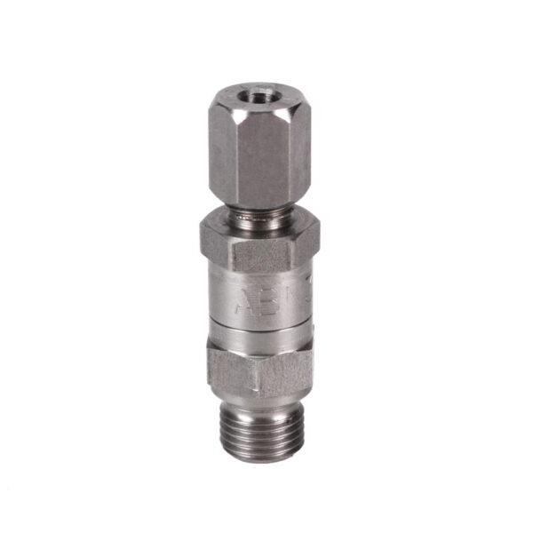
| Air inlet connection | 169-000-183: M8x1 169-000-253: M10x1 |
|
| Oil inlet connection | M8x1 | |
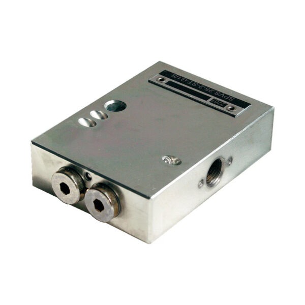
| Dimensions | 169-000-183: 128 x ∅36 mm 169-000-253: 139.5 x 41 mm |
5 x ∅1.41 inches 5.5 x 1.6 inches |
| Installation position | vertical | |
| Part number | Number of outputs |
| 169-000-182 | 2 |
| 169-000-183 | 3 |
| 169-000-184 | 4 |
| 169-000-185 | 5 |
| 169-000-186 | 6 |
| 169-000-252 | 2 |
| 169-000-253 | 3 |
| 169-000-254 | 4 |
| 169-000-255 | 5 |
| 169-000-256 | 6 |