Adjustable limiter 242

For circulating oil lubrication systems

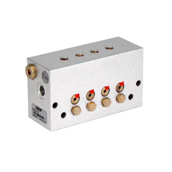
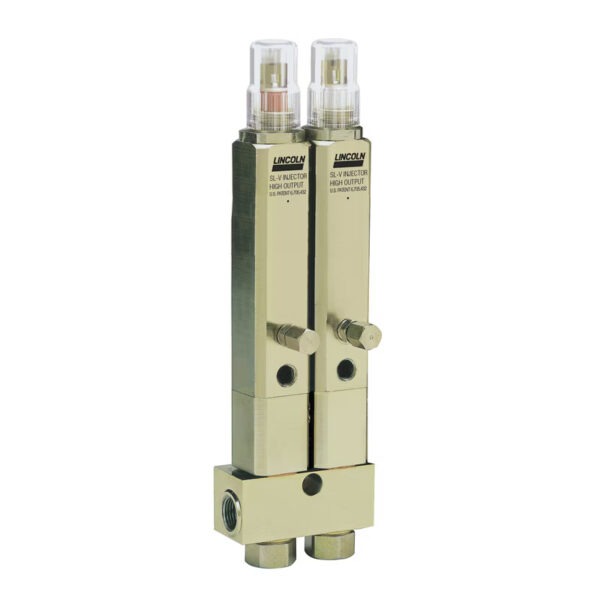
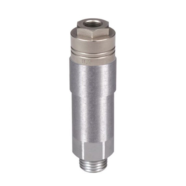
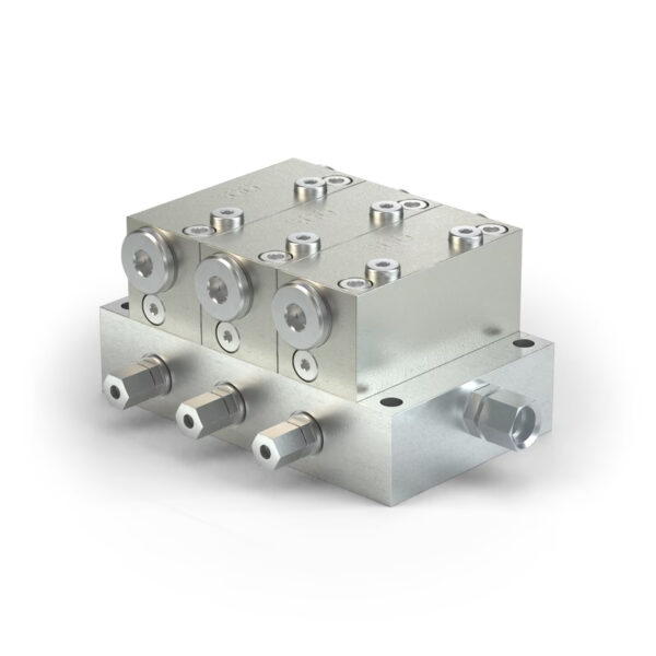
Adjustable flow limiters 242 are used when subsequent flow adjustment is required. These limiters are available in three versions, differing in dosing volume, visual flow indication, and number of outlets.

Type A — flow rates in the drip feed range from 0 to 0.01 l/min (0 to 0.02 pints). The 242 adjustable limiter is available with 1 to 14 outputs and a viewing window for flow monitoring. Type B offers a constant dosing volume from 0.01 to 1.0 l/min (0.02 to 2.11 pints) and is equipped with 2 to 12 outputs. Type C — dosing volume range from 0.01 to 2.0 l/min (0.02 to 4.23 pints). Depending on the distributor, versions with 2 to 6 outlets are available. Types B and C feature a spring-loaded metal pin in the inspection window for visual monitoring of oil flow.

Technical characteristics and advantages

  • Easy adjustment
  • Easy planning and flow control
  • Economical visual monitoring of oil consumption
  • Individual adjustment of the flow range for each lubrication point
  • Wide range of lubricant viscosity

areas of application

  • Oil and gas industry
  • Machine tools
  • Manufacturing of metal structures
  • Metal forming
  • Textile industry
Brochures and manuals

Description

Technical specifications
Operating principle adjustable limiter
Lubricant mineral and synthetic oils
Viscosity 10–1000 mm2/With
Exits
A 1, 2, 5, 14
B 2, 3, 4, 5, 6, 10, 12
C from 2 to 6
Dosage volume
A 0–0.01 l/min 0–0.02 pints/min
B 0.01–1.0 l/min 0.02–2.11 pints/min
C 0.01–2.0 l/min 0.02–4.23 pints/min
Operating temperature from 0 to 60 °C from 32 to 122 °F
Working pressure 10 bar 145 psi
Filter < 10 µm
Material steel
Compound A and B: M10×1 for 6mm pipe
C: M16×1.5 for 10mm pipe
Dimensions min. 93 × 16 × 32 mm
max. 97 × 25 × 253 mm
min. 3.66 x 0.63 x 1.29 in
max 3.82 x 0.98 x 9.96 inches
Installation position
A vertical relative to the sight glass, above the lubrication point
B, C any
Ordering Information 242 Type A
Dosing volume: 0–10 cm30–0.6 inches3
Part number Exits
skf.com-0901d1968016eef6-242-02.00 242–016.00 1
242–026.00 2
242–056.00 5
242–146.00 14
Ordering Information 242 Type B
Dosing volume: 10–1000 cm30,6-61 inches3
Part number Exits
242-034-00 242–024.00  2
242–034.00 3
242–044.00 4
242–054.00 5
242–064.00 6
242–104.00 10
242–124.00 12
Ordering Information 242 Type C
Dosing volume: 10–2000 cm30,6-122 inches3
Part number Exits
242-044-004 242–025.00 2
242–035.00  3
242–045.00 4
242–055.00 5
242–065.00 6

Configure the product, download the CAD file

Accessories

242, Type A and B, Main Pipe Connection and Accessories
Part number Description Pipeline, ∅ [mm]
406–162 connection for a main pipeline 6
408–162 connection for a main pipeline 8
410–162  connection for a main pipeline 10
408–211 threaded plug
508-215-CU washer
242, Type C, Main Pipe Connection and Accessories
Part number Description Pipeline, ∅ [mm]
410–018 connection for a main pipeline 10
412–018 connection for a main pipeline 12
412–011 threaded plug
DIN7603-A18×22-CU washer