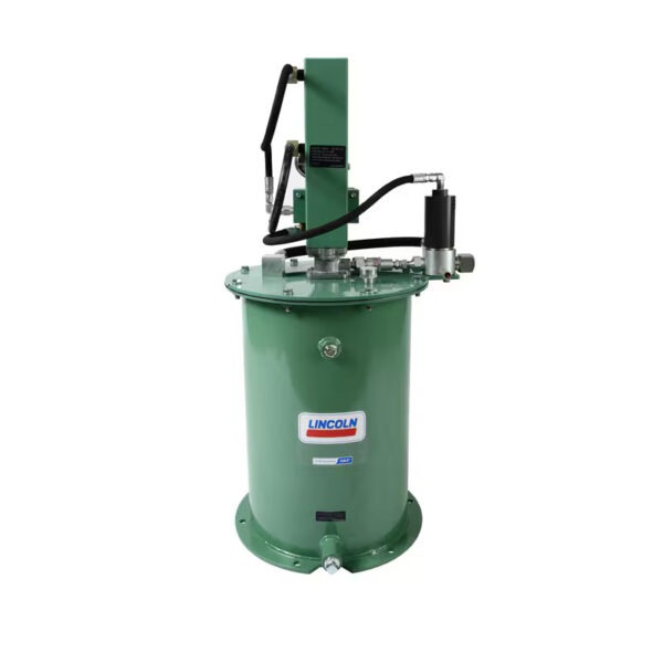
Description
| Operating principle | gear pump unit with electric drive, single circuit | |
| Lubricant | synthetic oils | |
| Working viscosity | 5–2000 mm2/With | |
| Consumption | 0.12–0.5 l/min | 0.25–1.06 pints/min |
| Number of lubricant outlets | 1 | |
| Ambient temperature | from +10 to +40 °C | from +50 to +104 °F |
| Oil temperature | from +10 to +65 °C | from +50 to +149 °F |
| Working back pressure | max 65 bar | 940 psi |
| Suction height | 500 mm | 19.68 inches |
| Drive speed | 2600–2700 min-1 | |
| Electric motor1) | 3-phase electric motor | |
| Voltage | 220–240 / 380–420 VAC, 50 Hz | |
| Nominal power | 0.075–0.18 kW | |
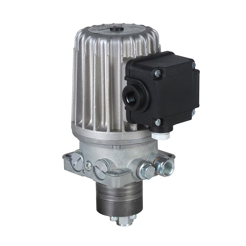
| Pressure connection | M 14 × 1.5 for ∅ 8 mm | |
| Seal material | NBR, FPM | |
| Tank | 2.7; 6; 15; 50 liters | 5.7; 12.7, 31.7; 105 pints |
| Tank material | plastic, metal | |
| Protection class | IP 54 | |
| Dimensions | min. 131 × 88 × 209 mm max. 131 × 88 × 220 mm |
min. 5.16 x 3.54 x 8.23 inches max 5.16 x 3.54 x 8.66 inches |
| Installation position | horizontal 2) or vertical | |
| Certificates (depending on model) | CE, UL, CSA | |
| Part number | Viscosity | Consumption1) | Working back pressure | Drive speed | Nominal power | Suction port thread | ||
| mm2/With | l/min | pints/min | bar | pounds per inch² | min-1 | kW | mm | |
| M1-2000+299 | 20–2000 | 0,12 | 0,25 | 28 | 406 | 2700 | 0 075 | M14×1.5 |
| M2-2004+299 | 20–2000 | 0,2 | 0,423 | 12 | 174 | 2700 | 0,075 | M14×1.5 |
| M2-2000+299 | 20–2000 | 0,2 | 0,423 | 28 | 406 | 2700 | 0,075 | M14×1.5 |
| M2-S14+299 | 20–1000 | 0,2 | 0,423 | 65 | 940 | 2700 | 0,075 | M14×1.5 |
| M2-2127+299 | 20–2000 | 0,2 | 0,423 | 70 | 1015 | 2700 | 0,075 | M14×1.5 |
| M5-2000+299 | 20–1000 | 0,5 | 1,06 | 28 | 406 | 2700 | 0,075 | M14×1.5 |
| M5-2024+299 | 20–2000 | 0,5 | 1,06 | 25 | 362 | 2700 | 0,075 | M14×1.5 |
| M5-2013+299 | 5–500 | 0,5 | 1,06 | 16 | 230 | 2700 | 0,075 | M14×1.5 |
| M5-S12+299 | 35–500 | 0,5 | 1,06 | 60 | 870 | 2700 | 0,120 | M14×1.5 |
| M10-2002+299 | 10–500 | 1,0 | 2,12 | 15 | 217 | 2700 | 0,075 | M16×1.5 |
| Part number | Viscosity | Consumption1) | Working back pressure | Drive speed | Nominal power | Threaded connection of the suction channel | ||
| mm2/With | l/min | pints/min | bar | pounds per inch² | min-1 | kW | mm | |
| MF1-2000+299 | 20–2000 | 0,12 | 0,25 | 28 | 406 | 2700 | 0,075 | M14×1.5 |
| MF1-2006+299 | 20–2000 | 0,12 | 0,25 | 6 | 87 | 2700 | 0,075 | M14×1.5 |
| MF2-2000+299 | 20–2000 | 0,2 | 0,423 | 28 | 406 | 2700 | 0,075 | M14×1.5 |
| MF2-S12+299 | 20–1000 | 0,2 | 0,423 | 65 | 940 | 2800 | 0,120 | M14×1.5 |
| MF2-2127+299 | 140–1000 | 0,2 | 0,423 | 60 | 870 | 2700 | 0,075 | M14×1.5 |
| MF5-2000+299 | 20–1000 | 0,5 | 1,06 | 28 | 406 | 2700 | 0,075 | M14×1.5 |
| MF5-2014+299 | 5–500 | 0,5 | 1,06 | 12 | 174 | 2700 | 0,075 | M14×1.5 |
| MF5-S12+299 | 140–1000 | 0,5 | 1,06 | 60 | 870 | 2800 | 0,075 | M14×1.5 |
| Part number | Consumption | Tank capacity | Description | ||
| l/min | pints/min | l | pints | ||
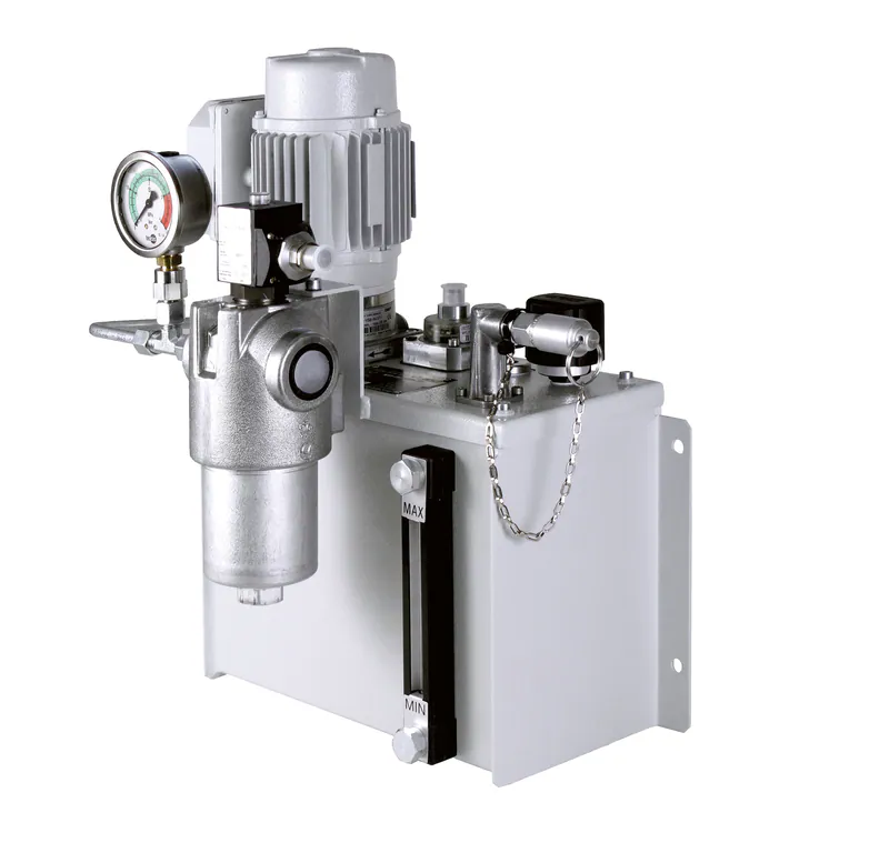
| MF1-BW3-S20+1FV | 0,12 | 0,25 | 2,7 | 5,7 | metal tank, wall mounting, warning when minimum fill level is reached |
| MF1-KW3-S15+1FX | 0,12 | 0,25 | 2,7 | 5,7 | Plastic tank, wall mounting, low water level warning, with pressure gauge |
| MF2-BW7+299 | 0,20 | 0,42 | 6 | 12,7 | metal tank, wall mounting, warning when minimum fill level is reached |
| MF2-KW6-S8+299 | 0,20 | 0,42 | 6 | 12,7 | plastic tank, wall mounting, pressure filter |
| MF5-BW7+140 | 0,50 | 1,0 | 6 | 12,7 | metal tank, wall mounting, warning when minimum fill level is reached |
| MF5-KW6+299 | 0,50 | 1,0 | 6 | 12,7 | Plastic tank, floor-standing design, minimum fill level warning |
| MF5-BW16-S223+299 | 0,50 | 1,0 | 15 | 31,7 | metal tank, floor-standing design, warning of reaching the min. and max. fill level |
| MF5-BW51-S22+29G | 0,50 | 1,0 | 50 | 105 | Metal tank, floor-standing design, minimum and maximum fill level warning, pressure filter, pressure gauge |