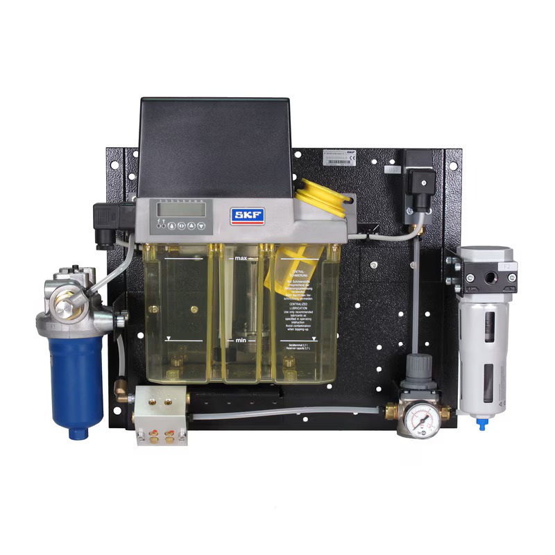
Description
| Operating principle | Oil-air lubrication unit with compact gear pump unit and mixing valve | |
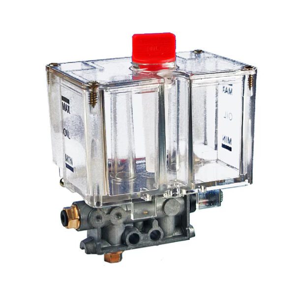
| MFL gear pump unit | ||
| Lubricant | Mineral or synthetic oil compatible with butadiene acrylonitrile rubber, viscosity from 20 to 1000 mm²/s (cSt) | |
| Feed volume | 0.2 l/min | 0.05 gallons/min |
| Number of outputs | 1–8 | |
| Working pressure | 30 bar | 435 psi |
| Ambient temperature | from +10 to +40 °C | from +50 to +104 °F |
| Supply voltage | 115/230 VAC; 24 VDC | |
| Rated current at 50 Hz | 1.06/0.53 A | |
| Rated current at 60 Hz | 1.36/0.68 A | |
| Nominal current at 24VDC | 1.6 A | |
| Power at 50 Hz | 60 W | |
| Power at 60 Hz | 75 W | |
| Power at 24VDC | 39 W | |
| Capacity of a plastic tank | 3 l | |
| Tank material | Polyamide (PA6) | |
| Protection class | IP 54 | |
| Pressure relief valve | included in the kit | |
| Thermal switch | included in the kit | |
| Operating mode (according to VDE 0530) | Standard design: S3, working time 20 % (from 1.25 to 25 min) | |
| Installation position | vertical | |
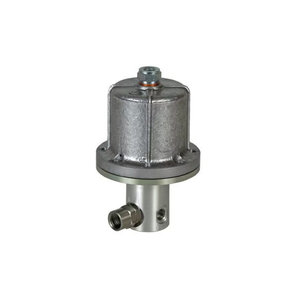
| Oil pressure switch (part of the gear pump unit) | ||
| Operating principle | Normally open contact | |
| Switching voltage range | 10-25 VAC; 10-36 VAC | |
| Switching current (resistive load) | ≤ 1 A | |
| Switching capacity (resistive load) | ≤ 10 W | |
| Nominal pressure | 20 bar | 290 psi |
| Lubricant level sensor (part of the gear pump unit) | ||
| Operating principle | Normally closed contact (opens when the filling level is too low) | |
| Switching voltage range | 10-25 VAC; 10-36 VAC | |
| Switching current (resistive load) | ≤ 0.25 A | |
| Switching capacity (resistive load) | ≤ 3 W | |
| Control unit | ||
| Type | IG54-20-S4-I | |
| Supply voltage | 115/230 VAC (50/60 Hz) selectable; 24 VDC | |
| Pump duty cycle limitation | 60 sec (not adjustable) | |
| Time interval | 10 min (adjustable from 1 to 99 min) | |
| Pump stop delay time | 5 sec (adjustable from 1 to 99 sec) | |
| Pre-lubrication cycles | 10 (adjustable from 0 to 99 cycles) | |
| Minimum air pressure switch | ||
| Operating principle | Normally closed contact / normally open contact (depending on the wiring diagram) | |
| Switching pressure | 0.5–5 bar (preset 3 bar) | 7.25–72.5 psi (preset 43.5 psi) |
| Max. switching voltage | 250 V | |
| Max. switching current | 5 A | |
| Reset differential | About 15 % | |
| 3/2-way directional control pneumatic valve | ||
| Switching voltage | 120V AC, 60Hz; 230V AC, 50Hz; 24V DC | |
| Switching capacity | 4 W | |
| Plug connector | DIN EN 175301-803-C | |
| Pressure range | 0–10 bar | 0–145 psi |
| Pneumatic control valve | ||
| Type | Diaphragm regulator | |
| Max. primary pressure | 0–16 bar | 0–232 psi |
| Secondary pressure | 0.5–10 bar | 7.25–145 psi |
| Seal material | NBR | |
| Pneumatic control valve including filter and moisture separator | ||
| Filter mesh | 5 microns | |
| Water separation | semi-automatic | |
| Oil filter | ||
| Filter mesh | 3 µm or 10 µm | |
| Contamination retention | 6.3 g at ∆p = 5 bar (3 µm) 5.2 g at ∆p = 5 bar (10 µm) |
|
| Oil contamination level indicator | ||
| Operating principle | Normally closed contact = alarm 100 % Normally open contact = warning signal 75 % |
|
| Max. switching voltage | 24 V AC/DC | |
| Max. switching capacity | 15 W | |
| Breaking capacity (resistive load) | 1 A (at 15 V AC/DC) | |
| Opening pressure | ∆5 bar –10 % | ∆72.5 lb/in² –10 % |
| The product can be configured using a configuration code. The order template includes the applicable part number and an explanation. | |
| OLA1-1E0XA30000000 |
|
| You can configure your product using the CAD configurator below. This will provide you with a specific order number. More detailed information is available in the product catalog. | |
Configure the product, download the CAD file